Products
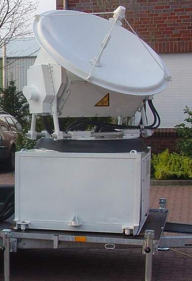
 Fig. 1. Scanning meteorological Ka-band polarimetric radar
Radar Characteristics
The radar is intended for volumetric observation, real-time measurements, imaging, and storing of
- Radar reflectivity profiles at co- and cross-polarizations,
- Radial mean velocity profiles at co- and cross-polarizations,
- Velocity variance at co- and cross-polarizations,
- Doppler spectrum at co- and cross-polarizations,
- Linear depolarization ratio (LDR),
- The complete raw data, which are digitized signals from the I and Q receiver outputs.
These quantities are accessible in real time in various graphical and map forms on computer displays of local and remote users.
The radar measurements are performed with the following characteristics:
Measurement characteristics of the radar
| Minimum Height | 150, full sensitivity above 300 |
| Measuring Range, km | 7.5-50 |
| Range Resolution, m | 15, 30, and 60 |
| Doppler Velocity Resolution, m/sec | 0.05 |
| Maximal Unambiguous Velocity, m/sec | +/-20 |
| Maximum Sensitivity at 5 km (integration - 0.1 sec.), dBZ | -45 |
| Number of Gates (max) | 500 |
| Averaging time, sec | 0.05 - 60 |
| FFT Length | 256, 512 and 1024 |
| Number of Gates with Simultaneous Stored Raw Data | 500 |
| Minimum Dwell Time, sec | 0.1 |
| Antenna Beam Width | 0.52° x 0.52° |
| Polarisation isolation, dB | -35 |
The described radar operates in a pulsed mode and utilizes a coherent on receiver technique for Doppler measurements. The polarimetric measurements are realized by receiving and processing simultaneously backscattered signals at co- and cross-polarizations. The radar allows volumetric exploration by mechanical scanning of the antenna system. The main technical parameters of the radar are as following
Technical parameters of the radar.
| Frequency, GHz | 35.5+/-0.15 GHz |
| Peak Power (max), kW | 30 |
| Tube Type | magnetron |
| Pulse Width, ns | 100, 200 and 400 |
| Pulse Repetition Frequency, kHz | 2.5, 5 and 10 |
| Receiver noise figure, dB | 3.2 |
|
Losses, dB Transmitting path Receiving path |
1 2.5 |
| ADC Sampling Rate, MHz | 50 MHz |
| ADC Sampling Resolution, bit | 14 |
| Type of Bus for the Signal Processing Board | PCI 64 MHz |
| Operation System of the Host Computer | Linux or MS Windows |
| Network Protocol | TCP/IP |
| Antenna Diameter, m | 1.2 |
| Sidelobe Level, db | -25 |
| Precision for Antenna Positioning, deg | 0.1 |
|
Scan range, deg azimuth direction elevation direction |
-183...+183 -45...+45 |
| Scan velocity (max), both directions, deg/sec | 10 |
| Acceleration (max), both directions, deg2/sec | 10 |
| Supply Voltage | AC 230V+10%-15% 50Hz |
|
Power consumption: Transmitter receiver module Antenna heating Scanning unit |
1.1 kW 1.6 kW(max) 300 W |
| Weight | 140 kg |
The radar has a built-in permanent calibration system. The radar calibration is based on independent measurements of the transmitter and receiver parameters. For these purposes, the transmitter output power and receiver sensitivity are continuously measured. The receiver sensitivity is determined by means of measurements of the signal to noise ratio of an additional noise signal with a constant power level.
The radar has network capabilities to allow for remote radar control and data receiving through any network supporting the TCP/IP protocol, including the Internet. In order to provide the network services, a special radar server is developed and introduced. The server is working on the radar host computer under control of the Linux operating system. There is also a software package of Windows and Linux (2.4.xx kernel) programs for obtaining and visualising radar data via the Internet. Remote control and diagnostics of the radar operation from any network computer is made possible as well.
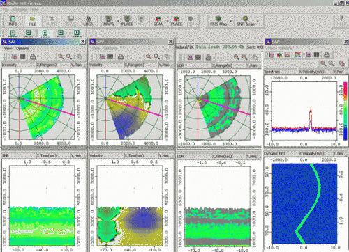
 Fig. 2. Example of configuration of the radar user display
An example of user screen of Scanning meteorological radar is shown in the figure above. The right windows display PPI scanning (upper one) and time-intensity range profile (lower one). Further, from the left to right the velocity and LDR data are shown in the same format. In the left windows the instantaneous spectrum (the upper window) and dynamical spectrum (the lower one) on the chosen altitude (2000 m) are shown.
